Pilar metálico OSP
El pilar metálico configurable OSP se puede utilizar para soportar cargas axiales en clase de servicio 3. El OSP está compuesto por un tubo circular y una pletina a elegir soldada en cada extremo.
Detalles de producto
Características
Materia
- Acero S235JR según la norma NF EN 10025-2. Galvanizado en caliente según la norma NF EN ISO 1461,
- Posible acabados : galvanización en caliente, pintura anticorrosión (utilización en interiror ), termolacado,
- Acero inoxidable bajo pedido.
Ventajas
- Resistencia a la compresión,
- Puede soportar cargas de levantamiento,
- Se puede utilizar en madera u hormigón,
- Las marcas de alineación en las pletinas facilitan su colocación,
- Pintura bajo pedido.
Datos técnicos
Descripción general del producto
El pilar OSP está compuesto por la combinación de un tubo y de pletinas soldadas en cada extremo; puede seleccionar entre 7 pletinas diferentes configurables. Los parámetros disponibles del tubo y de las pletinas se describen a continuación.
En las tablas indicadas a continuación, la resistencia característica de una configuración de OSP corresponde al mínimo de las resistencias de las pletinas seleccionadas. La comprobación del tubo y de las soldaduras está incluida en estas resistencias. Este producto se puede fijar en hormigón y en madera para soportar cargas axiales (compresión o tracción).
En las tablas indicadas a continuación, la resistencia característica de una configuración de OSP corresponde al mínimo de las resistencias de las pletinas seleccionadas. La comprobación del tubo y de las soldaduras está incluida en estas resistencias.
Para las pletinas SP6, 7 y 8 con una anchura A diferente de la anchura mostrada en las tablas, el usuario deberá considerar el mínimo de las resistencias de las dos anchuras más cercanas.
Las resistencias mostradas en estas tablas son resistencias características conforme a la norma EN1995-1-1 que se deberán multiplicar por el factor kmod y dividir por γm.
* La compresión se considera perpendicular a la veta de la madera, para una clase C24 o superior.
** Para las pletinas SP6, SP7 o SP8, el usuario deberá comprobar la tracción perpendicular a la veta de la madera.
*** El usuario deberá comprobar la resistencia de los anclajes.
Las resistencias a la compresión perpendicular a la veta de la madera R1.k solo son válidas si no hay carga concentrada a una distancia inferior a 2h, siendo h la altura de la viga. Las resistencias a la compresión perpendicular a la veta de la madera R1.k se pueden multiplicar por 1,16 si se utiliza madera laminada.
Encontrará más arriba el formulario para contactarnos.
SP4 Dimensiones
| Modelo | Dimensiones [mm] | Fijaciones | |||||||
|---|---|---|---|---|---|---|---|---|---|
| Part dimensions | Associated tube diam. G | Agujeros pletina | Sobre madera | Sobre hormigón | |||||
| A | B | Espesor | Cdad | Tipo | Cdad | Tipo | |||
| SP4/Ø89/80 | 80 | 160 | 4 | 89 | 2 Ø12 | 2 | Ø10 | 2 | Ø10 |
| SP4/Ø89/90 | 90 | 170 | 4 | 89 | 2 Ø12 | 2 | Ø10 | 2 | Ø10 |
| SP4/Ø89/100 | 100 | 180 | 4 | 89 | 2 Ø14 | 2 | Ø12 | 2 | Ø12 |
| SP4/Ø89/120 | 120 | 200 | 4 | 89 | 2 Ø14 | 2 | Ø12 | 2 | Ø12 |
| SP4/Ø102/90 | 90 | 170 | 4 | 102 | 2 Ø12 | 2 | Ø10 | 2 | Ø10 |
| SP4/Ø102/100 | 100 | 180 | 4 | 102 | 2 Ø14 | 2 | Ø12 | 2 | Ø12 |
| SP4/Ø102/120 | 120 | 200 | 4 | 102 | 2 Ø14 | 2 | Ø12 | 2 | Ø12 |
| SP4/Ø114/100 | 100 | 180 | 4 | 114 | 2 Ø14 | 2 | Ø12 | 2 | Ø12 |
| SP4/Ø114/120 | 120 | 200 | 4 | 114 | 2 Ø14 | 2 | Ø12 | 2 | Ø12 |
| SP4/Ø114/140 | 140 | 220 | 4 | 114 | 2 Ø18 | 2 | Ø16 | 2 | Ø16 |
| SP4/Ø114/150 | 150 | 230 | 4 | 114 | 2 Ø18 | 2 | Ø16 | 2 | Ø16 |
| SP4/Ø140/120 | 120 | 200 | 4 | 140 | 2 Ø14 | 2 | Ø12 | 2 | Ø12 |
| SP4/Ø140/140 | 140 | 220 | 4 | 140 | 2 Ø18 | 2 | Ø16 | 2 | Ø16 |
| SP4/Ø140/150 | 150 | 230 | 4 | 140 | 2 Ø18 | 2 | Ø16 | 2 | Ø16 |
SP5 Dimensions
| Modelo | Dimensiones [mm] | Fijaciones | |||||||
|---|---|---|---|---|---|---|---|---|---|
| Part dimensions | Associated tube diam. G | Agujeros pletina | Sobre madera | Sobre hormigón | |||||
| A | B | Espesor | Cdad | Tipo | Cdad | Tipo | |||
| SP5/Ø89/80 | 80 | 240 | 4 | 89 | 2 Ø12 | 2 | Ø10 | 2 | Ø10 |
| SP5/Ø89/90 | 90 | 250 | 4 | 89 | 2 Ø12 | 2 | Ø10 | 2 | Ø10 |
| SP5/Ø89/100 | 100 | 260 | 4 | 89 | 2 Ø14 | 2 | Ø12 | 2 | Ø12 |
| SP5/Ø89/120 | 120 | 280 | 4 | 89 | 2 Ø14 | 2 | Ø12 | 2 | Ø12 |
| SP5/Ø102/80 | 80 | 240 | 4 | 102 | 2 Ø12 | 2 | Ø10 | 2 | Ø10 |
| SP5/Ø102/90 | 90 | 250 | 4 | 102 | 2 Ø12 | 2 | Ø10 | 2 | Ø10 |
| SP5/Ø102/100 | 100 | 260 | 4 | 102 | 2 Ø14 | 2 | Ø12 | 2 | Ø12 |
| SP5/Ø102/120 | 120 | 280 | 4 | 102 | 2 Ø14 | 2 | Ø12 | 2 | Ø12 |
| SP5/Ø114/90 | 90 | 250 | 4 | 114 | 2 Ø12 | 2 | Ø10 | 2 | Ø10 |
| SP5/Ø114/100 | 100 | 260 | 4 | 114 | 2 Ø14 | 2 | Ø12 | 2 | Ø12 |
| SP5/Ø114/120 | 120 | 280 | 4 | 114 | 2 Ø14 | 2 | Ø12 | 2 | Ø12 |
| SP5/Ø114/140 | 140 | 300 | 4 | 114 | 2 Ø18 | 2 | Ø16 | 2 | Ø16 |
| SP5/Ø114/150 | 150 | 310 | 4 | 114 | 2 Ø18 | 2 | Ø16 | 2 | Ø16 |
| SP5/Ø140/120 | 120 | 280 | 4 | 140 | 2 Ø14 | 2 | Ø12 | 2 | Ø12 |
| SP5/Ø140/140 | 140 | 300 | 4 | 140 | 2 Ø18 | 2 | Ø16 | 2 | Ø16 |
| SP5/Ø140/150 | 150 | 310 | 4 | 140 | 2 Ø18 | 2 | Ø16 | 2 | Ø16 |
SP6 Dimensiones
| Modelo | Dimensiones [mm] | Fijaciones | ||||||
|---|---|---|---|---|---|---|---|---|
| Part dimensions | Associated tube diam. G | Agujeros pletina | Sobre madera | |||||
| A | B | C | Espesor | Cdad | Tipo | |||
| SP6/Ø89/75-90 | 75 - 90 | 230 | 195 - A/2 | 4 | 89 | 12 Ø9.5 | 12 | Ø8x40 |
| SP6/Ø89/91-115 | 91 - 115 | 255 | 207,5 - A/2 | 4 | 89 | 12 Ø9.5 | 12 | Ø8x40 |
| SP6/Ø89/116-129 | 116 - 129 | 282 | 221 - A/2 | 4 | 89 | 12 Ø9.5 | 12 | Ø8x40 |
| SP6/Ø102/75-90 | 75 - 90 | 230 | 195 - A/2 | 4 | 102 | 12 Ø9.5 | 12 | Ø8x40 |
| SP6/Ø102/91-115 | 91 - 115 | 255 | 207,5 - A/2 | 4 | 102 | 12 Ø9.5 | 12 | Ø8x40 |
| SP6/Ø102/116-142 | 116 - 142 | 282 | 221 - A/2 | 4 | 102 | 12 Ø9.5 | 12 | Ø8x40 |
| SP6/Ø114/91-115 | 91 - 115 | 255 | 207,5 - A/2 | 4 | 114 | 12 Ø9.5 | 12 | Ø8x40 |
| SP6/Ø114/116-142 | 116 - 142 | 282 | 221 - A/2 | 4 | 114 | 12 Ø9.5 | 12 | Ø8x40 |
| SP6/Ø140/116-142 | 116 - 142 | 282 | 221 - A/2 | 4 | 140 | 12 Ø9.5 | 12 | Ø8x40 |
SP7 Dimensiones
| Modelo | Dimensiones [mm] | Fijaciones | ||||||
|---|---|---|---|---|---|---|---|---|
| Part dimensions | Associated tube diam. G | Agujeros pletina | Sobre madera | |||||
| A | B | C | Espesor | Cdad | Tipo | |||
| SP7/Ø89/75-114 | 75-114 | A + 84 | 150 | 4 | 89 | 12 Ø9.5 | 12 | Ø8x40 |
| SP7/Ø89/115-129 | 115-129 | A + 84 | 150 | 4 | 89 | 12 Ø9.5 | 12 | Ø8x40 |
| SP7/Ø89/75-79 | 75-79 | A + 84 | 150 | 4 | 89 | 12 Ø9.5 | 12 | Ø8x40 |
| SP7/Ø89/80-89 | 80-89 | A + 84 | 150 | 4 | 89 | 12 Ø9.5 | 12 | Ø8x40 |
| SP7/Ø89/90-99 | 90-99 | A + 84 | 150 | 4 | 89 | 12 Ø9.5 | 12 | Ø8x40 |
| SP7/Ø89/100-114 | 100-114 | A + 84 | 150 | 4 | 89 | 12 Ø9.5 | 12 | Ø8x40 |
| SP7/Ø89/115-119 | 115-119 | A + 84 | 150 | 4 | 89 | 12 Ø9.5 | 12 | Ø8x40 |
| SP7/Ø89/120-129 | 120-129 | A + 84 | 150 | 4 | 89 | 12 Ø9.5 | 12 | Ø8x40 |
| SP7/Ø102/90-99 | 90-99 | A + 84 | 150 | 4 | 102 | 12 Ø9.5 | 12 | Ø8x40 |
| SP7/Ø102/100-114 | 100-114 | A + 84 | 150 | 4 | 102 | 12 Ø9.5 | 12 | Ø8x40 |
| SP7/Ø102/115-119 | 115-119 | A + 84 | 150 | 4 | 102 | 12 Ø9.5 | 12 | Ø8x40 |
| SP7/Ø102/120-139 | 120-139 | A + 84 | 150 | 4 | 102 | 12 Ø9.5 | 12 | Ø8x40 |
| SP7/Ø114/100-139 | 100-139 | A + 84 | 150 | 4 | 114 | 12 Ø9.5 | 12 | Ø8x40 |
| SP7/Ø114/100-114 | 100-114 | A + 84 | 150 | 4 | 114 | 12 Ø9.5 | 12 | Ø8x40 |
| SP7/Ø114/115-119 | 115-119 | A + 84 | 150 | 4 | 114 | 12 Ø9.5 | 12 | Ø8x40 |
| SP7/Ø114/120-139 | 120-139 | A + 84 | 150 | 4 | 114 | 12 Ø9.5 | 12 | Ø8x40 |
| SP7/Ø114/140-142 | 140-142 | A + 84 | 150 | 4 | 114 | 12 Ø9.5 | 12 | Ø8x40 |
| SP7/Ø140/115-119 | 115-119 | A + 84 | 150 | 4 | 140 | 12 Ø9.5 | 12 | Ø8x40 |
| SP7/Ø140/120-139 | 120-139 | A + 84 | 150 | 4 | 140 | 12 Ø9.5 | 12 | Ø8x40 |
| SP7/Ø140/140-142 | 140-142 | A + 84 | 150 | 4 | 140 | 12 Ø9.5 | 12 | Ø8x40 |
SP8 Dimensiones
| Modelo | Dimensiones [mm] | Fijaciones | ||||||
|---|---|---|---|---|---|---|---|---|
| Part dimensions | Associated tube diam. G | Agujeros pletina | Sobre madera | |||||
| A | B | C | Espesor | Cdad | Tipo | |||
| SP8/Ø89/75-114 | 75-114 | A + 84 | 150 | 4 | 89 | 18 Ø9.5 | 18 | Ø8x40 |
| SP8/Ø89/115-129 | 115-129 | A + 84 | 150 | 4 | 89 | 18 Ø9.5 | 18 | Ø8x40 |
| SP8/Ø89/75-79 | 75-79 | A + 84 | 150 | 4 | 89 | 18 Ø9.5 | 18 | Ø8x40 |
| SP8/Ø89/80-89 | 80-89 | A + 84 | 150 | 4 | 89 | 18 Ø9.5 | 18 | Ø8x40 |
| SP8/Ø89/90-99 | 90-99 | A + 84 | 150 | 4 | 89 | 18 Ø9.5 | 18 | Ø8x40 |
| SP8/Ø89/100-114 | 100-114 | A + 84 | 150 | 4 | 89 | 18 Ø9.5 | 18 | Ø8x40 |
| SP8/Ø89/115-119 | 115-119 | A + 84 | 150 | 4 | 89 | 18 Ø9.5 | 18 | Ø8x40 |
| SP8/Ø89/120-129 | 120-129 | A + 84 | 150 | 4 | 89 | 18 Ø9.5 | 18 | Ø8x40 |
| SP8/Ø102/80-89 | 80-89 | A + 84 | 150 | 4 | 102 | 18 Ø9.5 | 18 | Ø8x40 |
| SP8/Ø102/90-99 | 90-99 | A + 84 | 150 | 4 | 102 | 18 Ø9.5 | 18 | Ø8x40 |
| SP8/Ø102/100-114 | 100-114 | A + 84 | 150 | 4 | 102 | 18 Ø9.5 | 18 | Ø8x40 |
| SP8/Ø102/115-119 | 115-119 | A + 84 | 150 | 4 | 102 | 18 Ø9.5 | 18 | Ø8x40 |
| SP8/Ø102/120-139 | 120-139 | A + 84 | 150 | 4 | 102 | 18 Ø9.5 | 18 | Ø8x40 |
| SP8/Ø114/100-114 | 100-114 | A + 84 | 150 | 4 | 114 | 18 Ø9.5 | 18 | Ø8x40 |
| SP8/Ø114/115-119 | 115-119 | A + 84 | 150 | 4 | 114 | 18 Ø9.5 | 18 | Ø8x40 |
| SP8/Ø114/120-139 | 120-139 | A + 84 | 150 | 4 | 114 | 18 Ø9.5 | 18 | Ø8x40 |
| SP8/Ø114/140-142 | 140-142 | A + 84 | 150 | 4 | 114 | 18 Ø9.5 | 18 | Ø8x40 |
| SP8/Ø140/115-119 | 115-119 | A + 84 | 150 | 4 | 140 | 18 Ø9.5 | 18 | Ø8x40 |
| SP8/Ø140/120-139 | 120-139 | A + 84 | 150 | 4 | 140 | 18 Ø9.5 | 18 | Ø8x40 |
| SP8/Ø140/140-142 | 140-142 | A + 84 | 150 | 4 | 140 | 18 Ø9.5 | 18 | Ø8x40 |
SP1 Valores característicos
| Modelo | Associated tube diam. G | R1,k - On timber*, perpendicular to the grain [kN] | R1,k - On timber, parallel to the grain [kN] | R1,k - On concrete [kN] | R2,k - On concrete*** [kN] |
|---|---|---|---|---|---|
| SP1/Ø89 | 89 | 56.8 | 141.6 | 116.9 | 14.8 |
| SP1/Ø102 | 102 | 66.4 | 196.6 | 132.7 | 14.7 |
| SP1/Ø114 | 114 | 77.1 | 229.8 | 144.1 | 13.2 |
| SP1/Ø140 | 140 | 97.2 | 309.6 | 174.2 | 13 |
SP2 Valores característicos
| Modelo | Associated tube diam. G | R1,k - On timber*, perpendicular to the grain [kN] | R1,k - On timber, parallel to the grain [kN] | R1,k - On concrete [kN] | R2,k - On concrete*** [kN] |
|---|---|---|---|---|---|
| SP2/Ø89 | 89 | 27.3 | - | 93.9 | 10.7 |
| SP2/Ø102 | 102 | 32.5 | - | 107.1 | 10.7 |
| SP2/Ø114 | 114 | 36 | - | 115.9 | 10.1 |
| SP2/Ø140 | 140 | 45.8 | - | 140.7 | 10.1 |
SP4 Valores característicos
| Modelo | Associated tube diam. G | R1,k - On timber*, perpendicular to the grain [kN] | R1,k - On timber, parallel to the grain [kN] | R1,k - On concrete [kN] | R2,k - On concrete*** [kN] |
|---|---|---|---|---|---|
| SP4/Ø89/80 | 89 | 52.3 | - | 64.2 | 4.1 |
| SP4/Ø89/90 | 89 | 58.1 | - | 73.8 | 4.1 |
| SP4/Ø89/100 | 89 | 64.3 | - | 82.2 | 4.5 |
| SP4/Ø89/120 | 89 | 78.7 | - | 92.2 | 4.5 |
| SP4/Ø102/90 | 102 | 60.6 | - | 73.4 | 4.6 |
| SP4/Ø102/100 | 102 | 67.2 | - | 84.1 | 5.1 |
| SP4/Ø102/120 | 102 | 80.9 | - | 100.8 | 5 |
| SP4/Ø114/100 | 114 | 66.7 | - | 79.1 | 5.8 |
| SP4/Ø114/120 | 114 | 80.2 | - | 100.8 | 5.6 |
| SP4/Ø114/140 | 114 | 96.3 | - | 115.2 | 6.4 |
| SP4/Ø114/150 | 114 | 104.4 | - | 116.6 | 6.2 |
| SP4/Ø140/120 | 140 | 82.2 | - | 96.1 | 7.5 |
| SP4/Ø140/140 | 140 | 99.7 | - | 121.4 | 8.3 |
| SP4/Ø140/150 | 140 | 107.1 | - | 131.7 | 8 |
Total load bearing capacity is given, if two timber parts are connected with SP4 with equal contact area with the plate, then the load applied on each part shall not exceed 1/2 of the total load bearing capacity. If one timber part is only in contact on the overhang aisle of the plate then the load applied on this part shall not exceed 0.28 times the total load bearing capacity, the load applied on the other part in contact with the rest of the plate shall not exceed 0.72 times the total load bearing capacity.
SP5 Valores característicos
| Modelo | Associated tube diam. G | R1,k - On timber*, perpendicular to the grain [kN] | R1,k - On timber, parallel to the grain [kN] | R1,k - On concrete [kN] | R2,k - On concrete*** [kN] |
|---|---|---|---|---|---|
| SP5/Ø89/80 | 89 | 43.3 | 106.9 | 64.2 | 4 |
| SP5/Ø89/90 | 89 | 49.7 | 106.9 | 73.8 | 4.1 |
| SP5/Ø89/100 | 89 | 56.1 | 141.6 | 82.2 | 4.5 |
| SP5/Ø89/120 | 89 | 68.8 | 141.6 | 92.2 | 4.5 |
| SP5/Ø102/80 | 102 | 43.7 | 107.4 | 61.7 | 4.6 |
| SP5/Ø102/90 | 102 | 50.5 | 122.1 | 73.4 | 4.6 |
| SP5/Ø102/100 | 102 | 57.3 | 122.1 | 84.1 | 5.1 |
| SP5/Ø102/120 | 102 | 71 | 186.6 | 100.8 | 5 |
| SP5/Ø114/90 | 114 | 48.7 | 120 | 67.2 | 5.4 |
| SP5/Ø114/100 | 114 | 56 | 137.4 | 79.9 | 5.8 |
| SP5/Ø114/120 | 114 | 70.7 | 137.4 | 101.6 | 5.6 |
| SP5/Ø114/140 | 114 | 85.3 | 229.8 | 116 | 6.4 |
| SP5/Ø114/150 | 114 | 92.6 | 229.8 | 117.4 | 6.2 |
| SP5/Ø140/120 | 140 | 69.9 | 168 | 96.1 | 7.5 |
| SP5/Ø140/140 | 140 | 86.4 | 168 | 121.4 | 8.3 |
| SP5/Ø140/150 | 140 | 94.7 | 289.3 | 131.7 | 8 |
The capacities on timber perpendicular to the grain is valid if the plate is used as a intermediate support. For other configuration, please refer to ETA.
SP6 Valores característicos
| Modelo | Associated tube diam. G | R1,k - On timber*, perpendicular to the grain [kN] | R1,k - On timber, parallel to the grain [kN] | R2,k - On timber (fasteners Ø8) ** [kN] |
|---|---|---|---|---|
| SP6/Ø89/75-90 | 89 | 57.6 | - | 26.3 |
| SP6/Ø89/91-115 | 89 | 70.1 | - | 26.3 |
| SP6/Ø89/116-129 | 89 | 90.9 | - | 26.3 |
| SP6/Ø102/75-90 | 102 | 59.2 | - | 26.3 |
| SP6/Ø102/91-115 | 102 | 72.3 | - | 26.3 |
| SP6/Ø102/116-142 | 102 | 94.3 | - | 26.3 |
| SP6/Ø114/91-115 | 114 | 71.4 | - | 26.3 |
| SP6/Ø114/116-142 | 114 | 94.6 | - | 26.3 |
| SP6/Ø140/116-142 | 140 | 96.1 | - | 26.3 |
The capacities on timber perpendicular to the grain is valid if the plate is used as a intermediate support. For other configuration, please refer to ETA.
SP7 Valores característicos
| Modelo | Associated tube diam. G | R1,k - On timber*, perpendicular to the grain [kN] | R1,k - On timber, parallel to the grain [kN] | R2,k - On timber (fasteners Ø8) ** [kN] |
|---|---|---|---|---|
| SP7/Ø89/75-114 | 89 | 57.6 | - | 26.3 |
| SP7/Ø89/115-129 | 89 | 90.9 | - | 26.3 |
| SP7/Ø89/75-79 | 89 | 57.6 | - | 26.3 |
| SP7/Ø89/80-89 | 89 | 61.8 | - | 26.3 |
| SP7/Ø89/90-99 | 89 | 70.1 | - | 26.3 |
| SP7/Ø89/100-114 | 89 | 78.4 | - | 26.3 |
| SP7/Ø89/115-119 | 89 | 90.9 | - | 26.3 |
| SP7/Ø89/120-129 | 89 | 95 | - | 26.3 |
| SP7/Ø102/90-99 | 102 | 72.3 | - | 26.3 |
| SP7/Ø102/100-114 | 102 | 81.1 | - | 26.3 |
| SP7/Ø102/115-119 | 102 | 94.3 | - | 26.3 |
| SP7/Ø102/120-139 | 102 | 98.7 | - | 26.3 |
| SP7/Ø114/100-139 | 114 | 79.9 | - | 26.3 |
| SP7/Ø114/100-114 | 114 | 79.9 | - | 26.3 |
| SP7/Ø114/115-119 | 114 | 93.8 | - | 26.3 |
| SP7/Ø114/120-139 | 114 | 98.4 | - | 26.3 |
| SP7/Ø114/140-142 | 114 | 116.9 | - | 26.3 |
| SP7/Ø140/115-119 | 140 | 96.1 | - | 26.3 |
| SP7/Ø140/120-139 | 140 | 101.2 | - | 26.3 |
| SP7/Ø140/140-142 | 140 | 121.6 | - | 26.3 |
Total load bearing capacity is given, if two timber parts are connected with SP7 with equal contact area with the plate, then the load applied on each part shall not exceed 1/2 of the total load bearing capacity. If one timber part is only in contact on the overhang aisle of the plate then the load applied on this part shall not exceed 0.3 times the total load bearing capacity, the load applied on the other part in contact with the rest of the plate shall not exceed 0.7 times the total load bearing capacity.
SP8 Valores característicos
| Modelo | Associated tube diam. G | R1,k - On timber*, perpendicular to the grain [kN] | R1,k - On timber, parallel to the grain [kN] | R2,k - On timber (fasteners Ø8) ** [kN] |
|---|---|---|---|---|
| SP8/Ø89/75-114 | 89 | 61.8 | - | 39.4 |
| SP8/Ø89/115-129 | 89 | 81.5 | - | 39.4 |
| SP8/Ø89/75-79 | 89 | 61.8 | - | 39.4 |
| SP8/Ø89/80-89 | 89 | 63.7 | - | 39.4 |
| SP8/Ø89/90-99 | 89 | 66.6 | - | 39.4 |
| SP8/Ø89/100-114 | 89 | 70.8 | - | 39.4 |
| SP8/Ø89/115-119 | 89 | 81.5 | - | 39.4 |
| SP8/Ø89/120-129 | 89 | 85 | - | 39.4 |
| SP8/Ø102/80-89 | 102 | 69.4 | - | 39.4 |
| SP8/Ø102/90-99 | 102 | 73.1 | - | 39.4 |
| SP8/Ø102/100-114 | 102 | 75.5 | - | 39.4 |
| SP8/Ø102/115-119 | 102 | 81.5 | - | 39.4 |
| SP8/Ø102/120-139 | 102 | 85 | - | 39.4 |
| SP8/Ø114/100-114 | 114 | 82.7 | - | 39.4 |
| SP8/Ø114/115-119 | 114 | 85.4 | - | 39.4 |
| SP8/Ø114/120-139 | 114 | 85.7 | - | 39.4 |
| SP8/Ø114/140-142 | 114 | 99.2 | - | 39.4 |
| SP8/Ø140/115-119 | 140 | 101.8 | - | 39.4 |
| SP8/Ø140/120-139 | 140 | 102.9 | - | 39.4 |
| SP8/Ø140/140-142 | 140 | 104.3 | - | 39.4 |
Total load bearing capacity is given, if three timber parts are connected with SP8 with equal contact area with the plate, then the load applied on each part shall not exceed 1/3 of the total load bearing capacity. If two timber part are connected, and one goes through the connector, then for this element SP6 capacity can be considered
Instalación
Montaje
Fijaciones
En hormigón (para las pletinas SP1 a SP5) :
Anclaje químico :
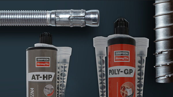
- Clase de servicio 1 o 2 : resina AT-HP y varilla roscada LMAS (M10, M12 o M16),
- Clase de servicio 3 : resina AT-HP y varilla roscada LMAS (M10, M12 o M16) A4.
Anclaje mecánico :
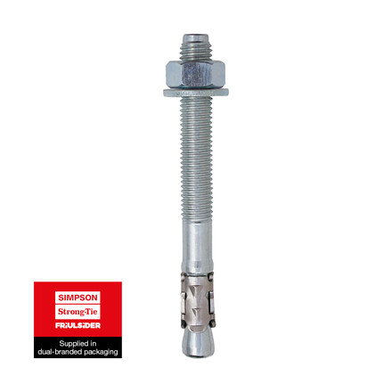
- Clases de servicio 1 y 2 : WA (M10, M12 o M16) o FM-753 CRACK 3DG (M10, M12 o M16) (-FMC bajo disposición parasísmica),
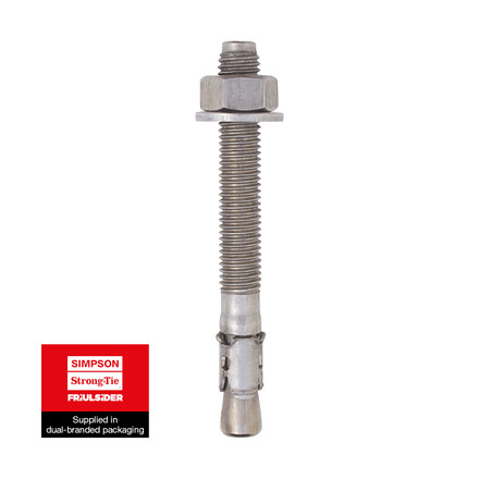
- Clase de servicio 3 : FM-753 A4 (M10 o M12)
En madera (para las pletinas SP6, SP7 y SP8) :
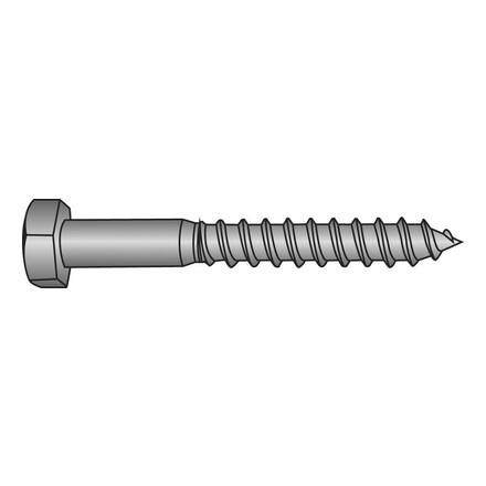
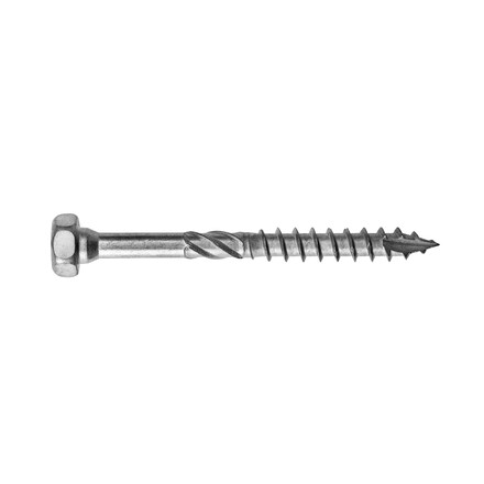
- Clases de servicio 1 y 2 : tirafondos con diámetro 8 o SSH8.0x40,
- Clase de servicio 3 : tirafondos de acero inoxidable con diámetro 8 o SSH8.0x40.
Instalación
- Oriente el pilar verticalmente en la estructura ayudándose de las marcas presentes en la pletina que permiten trazar el eje del tubo,
- Identifique sobre el soporte la posición de los anclajes al suelo,
- Perfore el soporte verticalmente, con el diámetro y la profundidad recomendados para las fijaciones elegidas,
- Fije la pletina inferior del pilar al suelo mediante los anclajes adaptados,
- Fije la pletina superior del pilar con la ayuda de tirafondos LAG o SSH8.0x40.
